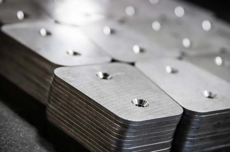
CNC machining for custom friction materials and brake components
FTL CNC machines friction materials and associated metallic components for new, existing and obsolete brake or motion-control applications.
The machining route is defined around the application, component geometry, material, interfaces and inspection requirements, not simply a part number or isolated drawing.
A trusted, accountable supplier since 2003
High-performance friction and braking solutions, backed by decades of in-house expertise and supplied to OEM and aftermarket customers worldwide.
Confirmed capability
Standards and registrations
Machine availability, geometry, dimensions, tolerances, quantities and inspection requirements must be confirmed for the individual component.
When FTL's CNC machining capability is the right route
Engage FTL when machining is part of a wider friction-material or component requirement rather than an isolated commodity purchase.
A new component needs to move from design into prototype manufacture
The application and required function are known, but the friction material, component geometry or repeatable production route still needs to be established: material selection or formulation, component engineering, prototype machining, bonding and finishing, testing and inspection, and transfer into repeat production.
An existing component needs a controlled repeat-production source
The customer has a drawing, specification or approved component but needs a connected manufacturing route covering machining, inspection, downstream processing and ongoing supply.
A legacy component must be redeveloped
The original supplier, drawing, material or finished component is no longer available. FTL can review the existing part and application before defining the geometry, material, machining, prototype and revalidation route.
A friction component is not performing as required
The engineering team is experiencing performance concerns: inconsistent braking, excessive or unpredictable wear, thermal-performance concerns or variation between components or production batches. The review may need to consider the component geometry, dimensions, friction material, bonding and manufacturing route together.
The friction material and associated metallic component must be manufactured together
The finished requirement may involve a machined friction component, a backing or associated metallic component, a bonded interface, surface preparation, finishing, assembly and dimensional inspection.
The current supply route has too many handovers
Machining is separated from material manufacture, bonding, finishing and inspection, creating unclear responsibility when dimensions, quality or component performance are questioned.
What FTL's CNC machining capability can support
The approved scope covers CNC machining of friction materials and associated metallic components.
The exact machine route, supplied material, geometry and inspection requirements must be established for each project.
Machined friction components
FTL can machine friction materials into component geometry defined around the application and agreed manufacturing route.
- Prototype friction components
- Components developed from approved drawings
- Components redeveloped from legacy information
- Custom pad or lining geometry
- Features required for bonding or assembly
- Repeat production following approval
- Dimensional inspection
Associated metallic components
Where the project requires a complete component, FTL can machine associated metallic elements within the agreed scope. The project must define:
- Material
- Component geometry
- Interfaces
- Surface preparation
- Finish
- Bonding requirements
- Inspection requirements
CNC routing
FTL's confirmed capability includes automatic CNC routers. The approved project scope should establish:
- Material reference and form
- Component geometry
- Required features
- Dimensional requirements
- Prototype or production quantity
- Inspection plan
Lathe-based machining
FTL's confirmed capability includes bar-fed lathes. The component, material, geometry, production quantity and downstream manufacturing stages must be reviewed before a machining route is confirmed.
Prototype component manufacture
CNC machining can support:
- Initial engineering samples
- Prototype components
- Comparative component variants
- Components for dimensional inspection
- Components for material or dynamic testing
- Components for customer evaluation
Repeat component manufacture
Following the agreed engineering and approval route, FTL can support:
- Controlled repeat machining
- Defined component revision
- In-process checks
- Final dimensional inspection
- Production documentation
- Batch or lot traceability
- Inventory and scheduled call-off
Machining linked to downstream production
The machined component can remain within FTL's connected route for surface preparation, bonding, UV curing where applicable, protective coating, paint finishing, assembly, testing, final inspection, packaging and delivery.
Confirm the component and machining requirements before production
| Capability field | Confirmed position | Project-specific information required |
|---|---|---|
| 01Materials machined | Friction materials and associated metallic components | |
| 02Confirmed machine categories | Automatic CNC routers and bar-fed lathes | |
| 03Component route | Prototype and controlled repeat manufacture | Quantity, configuration and approval status |
| 04Design inputs | Drawing, specification, existing component or application brief | |
| 05Geometry | Custom component geometry within confirmed capability | Dimensions, features and interfaces |
| 06Tolerances | Against agreed dimensional requirements | |
| 07Inspection | CMM, in-process checks and final inspection | Critical dimensions, frequency and records |
| 08Downstream processes | Bonding, preparation, finishing, assembly and testing where required | Component construction and specification |
| 09Production documentation | Batch, lot, production and inspection records within agreed scope | Required document pack |
| 10Supply route | Storage, call-off, packaging and global delivery | Quantity, schedule and identification |
What to bring to the first machining discussion
Start with what is available. FTL does not require every production detail to be final before the first conversation.
Application and component function
- What equipment or system the component belongs to
- What the component must do
- Whether it brakes, holds, locks, damps or controls motion
- What has prompted the enquiry
- Whether the component is already in service
Project starting point
Confirm whether the requirement relates to:
- A new component
- An existing drawing
- An existing physical part
- A prototype
- An obsolete component
- A performance problem
- A component moving into repeat manufacture
Available technical information
- Drawing
- Partial drawing
- CAD file
- Specification
- Existing component
- Photograph
- Material reference
- Current production information
- Inspection record
- Test information
Geometry and interfaces
Where known, identify:
- Overall component dimensions
- Relevant features
- Mounting or locating interfaces
- Mating surfaces
- Associated metallic elements
- Bonded areas
- Available installation space
- Features requiring dimensional control
Material information
- Existing friction-material reference
- Proposed material family
- Associated metallic-component material
- Customer-supplied material information
- Any current material data sheet
- Any material or component restrictions
Dimensional and inspection requirements
Where available, identify:
- Critical dimensions
- Tolerances
- Inspection frequency
- CMM requirements
- Required records
- Customer inspection or approval requirements
Downstream component requirements
Confirm whether the machined parts also require:
- Surface preparation
- Bonding
- Curing
- Protective coating
- Paint finishing
- Assembly
- Material or dynamic testing
- Shear testing
- Final inspection
Production and supply context
Later discussions can cover:
- Prototype quantity
- Expected annual volume
- Repeat-production schedule
- Inventory holding
- Scheduled call-off
- Packaging
- Labels and barcodes
- Export and delivery requirements
Expected annual volume and commercial scope are discussed after the application and technical fit have been established.
Design the component around material, manufacture and inspection
A component drawing should be reviewed alongside the material and complete manufacturing route.
A geometry that can be represented in CAD still needs to be assessed against how the component will be machined, bonded, finished, inspected and repeated.
Material form and component geometry
01The project should confirm:
- Material reference
- Material form
- Component geometry
- Required features
- Associated metallic elements
- Prototype and repeat-production requirements
Interfaces and mating surfaces
02Review:
- Mounting features
- Locating features
- Mating surfaces
- Available installation space
- Bonded interfaces
- Component orientation
- Assembly relationship
Bonding and surface-preparation requirements
03Where the component will be bonded, the engineering route should consider:
- Bonded area
- Associated backing component
- Surface preparation
- Finish before bonding
- Cure route
- Shear-testing requirements
- Final inspection
Finishing and protection
04Where applicable, define:
- Protective coating
- Paint finish
- Areas that must remain uncoated
- Customer identification
- Final surface requirements
- Packaging and handling requirements
Inspection access
05The component definition should identify:
- Critical dimensions
- Inspection surfaces
- Datum or reference requirements
- Inspection stage
- Required records
- Final acceptance responsibility
Prototype-to-production continuity
06The project should maintain alignment between:
- Approved material reference
- Approved component geometry
- Drawing or component revision
- Manufacturing route
- Inspection requirements
- Traceability
- Customer-approved configuration
A controlled CNC machining route from brief to repeat production
The sequence varies by project, but each stage should produce enough information to support the next engineering or manufacturing decision.
Establish technical fit
- Application
- Required component function
- Current project stage
- Drawing, specification or existing component
- Material information
- Immediate technical or supply concern
Confirm design and drawing responsibility
- Drawing or component revision
- Design authority
- Customer approval responsibility
- FTL engineering scope
- Required file formats
- Confidentiality and file-transfer process
Confirm the material and complete-component route
- Friction material
- Associated metallic components
- Component form
- Bonding requirements
- Finishing
- Inspection
- Testing
- Production and supply requirements
Define geometry and inspection requirements
- Component geometry
- Relevant interfaces
- Critical dimensions
- Agreed tolerances
- Inspection method
- Required records
- Acceptance responsibilities
Agree the prototype or initial-production plan
- Component configuration
- Material or geometry variants
- Quantity
- Machining route
- Downstream processes
- Dimensions to inspect
- Tests to complete
- Evidence required for the next decision
Machine the components
- Approved friction and associated metallic elements move through the applicable CNC route
- In-process checks can be completed at agreed stages
Inspect the machined components
- In-process dimensional checks
- CMM inspection
- Visual checks
- Review against the approved drawing or component definition
- Inspection records
Complete the connected manufacturing stages
- Surface preparation
- Bonding
- UV curing
- Coating or paint finishing
- Assembly
- Material, dynamic or shear testing
- Final inspection
Support customer validation or approval
- FTL provides the machining, manufacturing, testing and inspection evidence within its agreed scope
- The customer or appointed authority completes any equipment, system or regulatory work for which it is responsible
Establish controlled repeat manufacture
- Material reference and revision
- Component geometry and revision
- Machining stages
- Downstream processes
- Inspection requirements
- Production records
- Traceability
- Change-control responsibilities
Establish storage and scheduled supply
- Secure finished-goods storage
- Controlled inventory
- Scheduled call-off
- Customer-specific packaging
- Labels and barcodes
- Export documentation
- International delivery
Machining and dimensional inspection within one connected route
Dimensional requirements should be defined before manufacture and verified against the agreed component definition.
Critical dimensions
01The project should identify:
- Dimensions that affect fit or installation
- Interfaces
- Bonded surfaces
- Component thickness or profile where relevant
- Features requiring controlled location
- Customer-specific inspection points
In-process checks
02In-process checks can support confirmation that the component remains aligned with the agreed manufacturing route before additional work is completed. The exact checks and frequency must be agreed for the project.
CMM dimensional inspection
03FTL's confirmed capability includes CMM inspection. The inspection scope can define:
- Characteristics to measure
- Drawing or component revision
- Tolerance
- Inspection quantity or frequency
- Required records
- Acceptance responsibility
Final visual and assembly inspection
04Where the machined component progresses into a finished assembly, final checks can review:
- Visible component condition
- Bonded or assembled construction
- Applicable finish
- Customer-specific identification
- Final component configuration
Traceability
05The agreed route can include traceability across material, component revision, production batch, machining, bonding, finishing, inspection, storage and dispatch.
What a CNC machining engagement can deliver
The deliverables depend on the component and agreed project stage.
A machining engagement can produce prototype and repeat-production friction and associated metallic components, the connected bonded and finished component where required, the dimensional and inspection evidence to support it, and a controlled route into repeat manufacture and scheduled supply. The exact deliverables are defined for each component and project stage.
Prototype components are not production-approved until the required customer review and validation route is complete.
Carry the approved component route from prototype into repeat manufacture
A prototype proves only what has been assessed within the agreed configuration and evidence scope.
Moving into repeat production requires control of the material, component definition, manufacturing stages and inspection requirements.
Prototype stage
The prototype phase can establish:
- Whether the geometry can be manufactured
- Whether the component fits the intended assembly
- Which dimensions require further review
- Whether downstream bonding or finishing is appropriate
- Whether the component is suitable for agreed testing
- Whether another design or material iteration is required
Approval stage
Before repeat production begins, confirm:
- Approved material reference
- Approved component geometry
- Drawing or component revision
- Required testing and inspection
- Customer acceptance
- Final approval responsibilities
Production stage
The controlled route can define:
- Applicable CNC process
- Downstream manufacturing stages
- In-process checks
- Final inspection
- Production records
- Batch and lot traceability
- Change-control requirements
Supply stage
Where required, FTL can support:
- Finished-goods storage
- Scheduled call-off
- Customer-specific packaging
- Labels and identification
- Export documentation
- Worldwide delivery
Keep CNC machining connected to the complete friction component
A fragmented route can divide friction-material manufacture, machining, backing-component supply, bonding, finishing, testing and inspection among several organisations. FTL can connect the relevant stages through one accountable manufacturing chain, helping keep the approved material and component definition aligned with the finished product.
Single-source friction manufacturing. Machining stays connected to material formulation, engineering, bonding, finishing, testing and supply within one accountable route, so the approved component definition is held together from prototype through to repeat supply. The full model, and how it compares with a fragmented multi-supplier route, is set out on the single-source page.
Actual lead-time, procurement or cost benefits depend on your existing supplier arrangement and the agreed FTL scope.
CNC machining within three engineering project routes
Machining is usually one stage of a wider engineering project. Choose the route that matches where your component is now.
New Programme Support
Moving a new component from design into prototype manufacture, testing and controlled repeat production.
Legacy & Obsolete Component Reverse Engineering
Redeveloping a component where the original part, drawing, material or supplier is no longer available.
Friction System Performance Optimisation
Reviewing geometry, material and manufacturing route together when a component is not performing as required.
CNC-machined friction components for demanding industries
The machining route is determined by the individual application, component and evidence requirements.
Aerospace
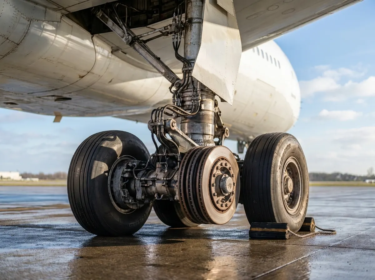
Machined friction and associated metallic components for braking, locking, actuation and motion-control applications where inspection, traceability and validation responsibilities must be clearly defined.
Aerospace Friction Materials & Components →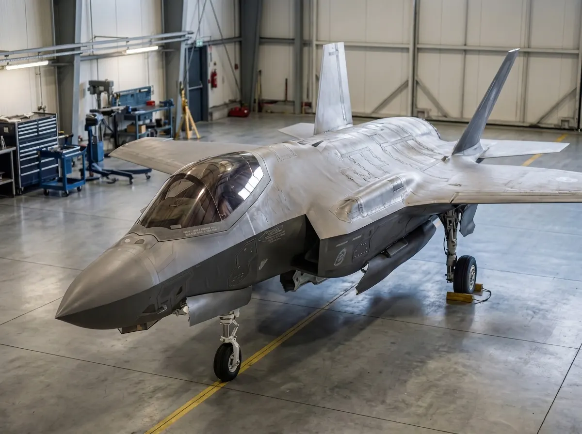
Defence
Connected component machining and manufacture for defence programmes where supplier assurance, inspection, documentation and supply continuity matter.
Defence Friction Materials & Components →
Wind Energy
Machined friction and complete-component support for yaw-brake programmes, obsolete components and performance-review projects.
Wind Turbine Friction Materials & Components →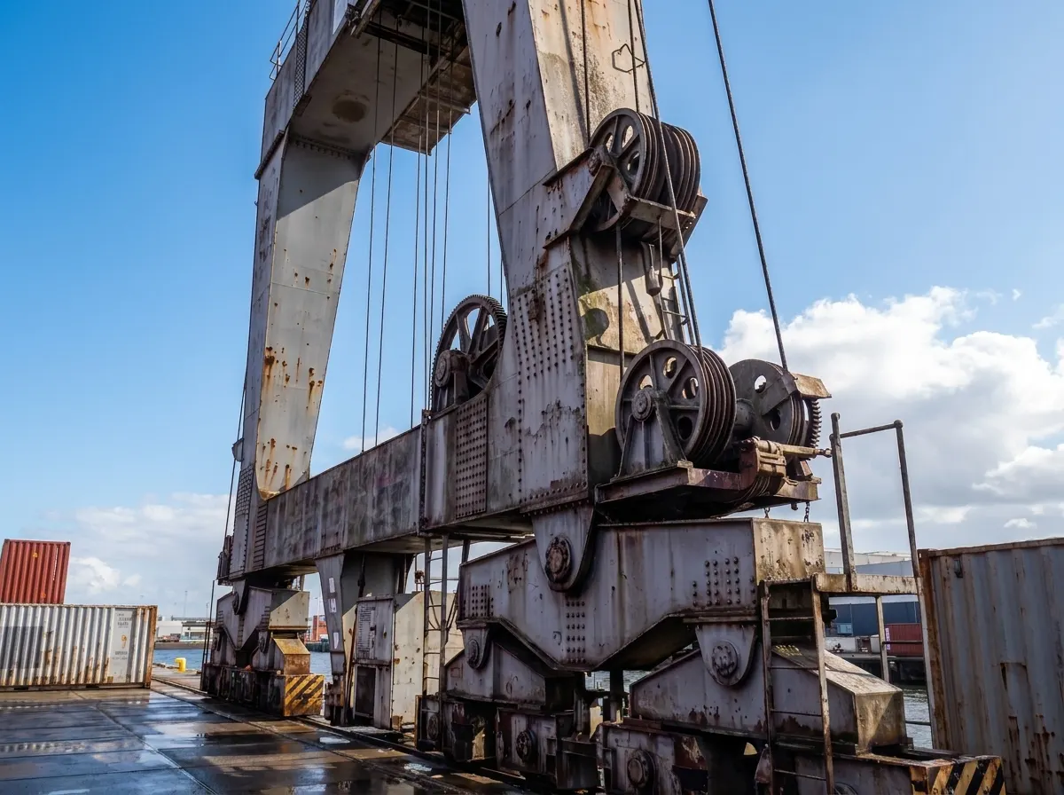
Industrial Equipment
Custom machined friction components for industrial braking, crane, motor, safety-equipment and motion-control applications.
Industrial Friction Materials & Components →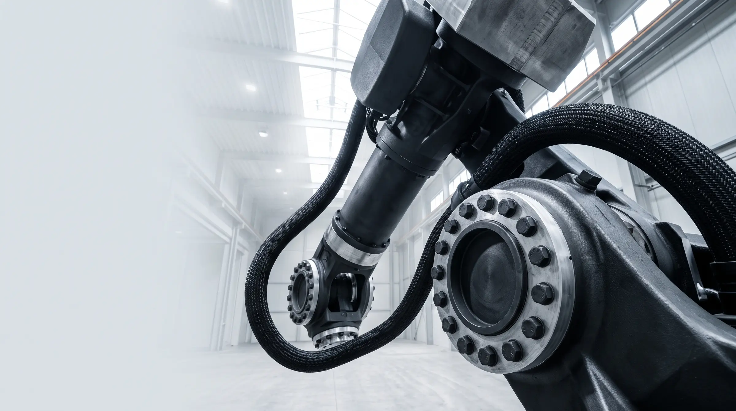
Robotics
Machined friction and associated components for robotic joint brakes, robotic arms and holding devices in industrial and collaborative robots.
Robotics Friction Materials & Components →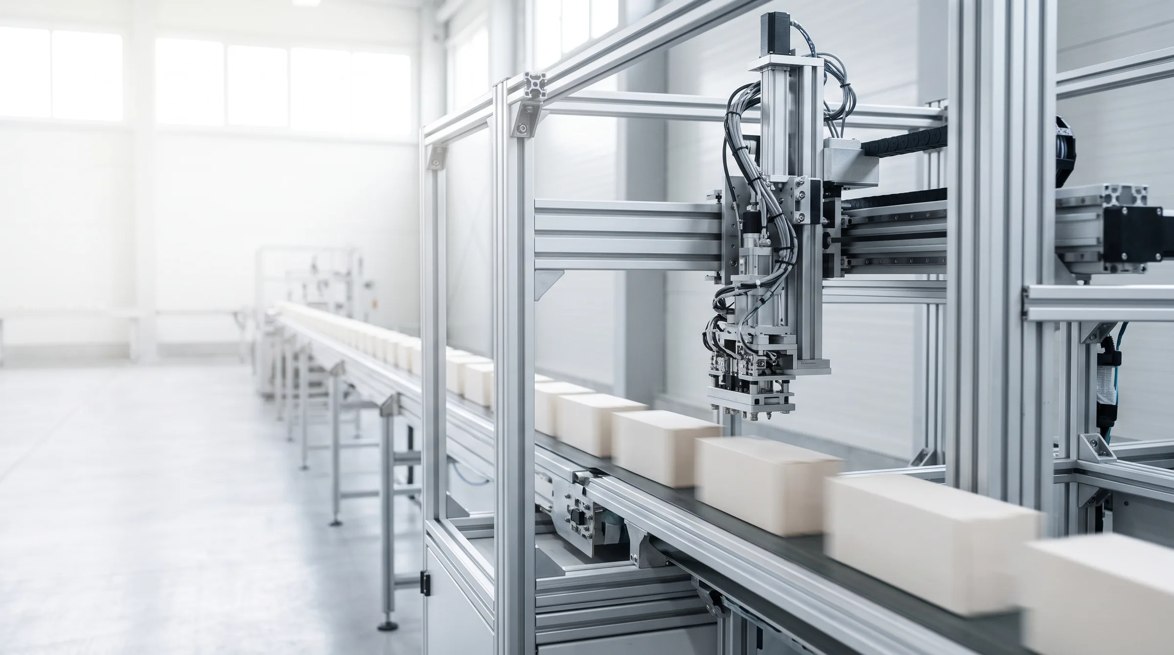
Industrial Automation
Machined brake and clutch components for servo motor brakes, linear actuators and automated handling equipment.
Automation Friction Materials & Components →CNC machining backed by connected engineering and inspection capability
SDTS approached FTL after an original aircraft brake pad became unavailable. FTL redesigned the pad, established an appropriate replacement-material route and manufactured the replacement component, supporting SDTS's route to a certifiable modification.
“The quality of the manufactured product is remarkable.”
Olivier Moulin 
Confirmed capability proof
- CNC machining of friction materials
- CNC machining of associated metallic components
- Automatic CNC routers
- Bar-fed lathes
- SolidWorks design support
- Prototype-to-production support
- CMM dimensional inspection
- In-process checks
- Bonding and finishing
- Batch and lot traceability
- Scheduled call-off and worldwide delivery
Company standards and registrations






The SDTS case demonstrates component engineering and manufacture.
Is FTL the right machining route for your component?
FTL is a strong fit when:
- The component is part of a brake or motion-control application
- The requirement involves a friction material or associated metallic component
- The material and component geometry need to be considered together
- A prototype must progress into repeat manufacture
- The component also requires bonding, finishing, testing or inspection
- An obsolete component needs to be redeveloped
- Dimensional inspection and traceability matter
- You want fewer suppliers across the connected manufacturing route
- The finished component needs inventory, call-off or international delivery
FTL must confirm fit when:
- The requirement is for one isolated subcontract process
- The material is customer-supplied
- The required metal grade has not been confirmed
- The geometry, tolerance or machine envelope is outside published information
- The requirement involves a currently unconfirmed machine process
- The project requires customer-specific inspection or approval standards
A different route may be more appropriate when:
- You need a generic online CNC quotation
- You need an unrelated metal component with no friction application
- You require an immediate stock item
- You are purchasing solely by part number
- No engineering or manufacturing review is required
- Price is the only selection criterion
Frequently asked questions about CNC machining friction components
What does FTL CNC machine?
Which CNC machine types does FTL use?
Can FTL machine both the friction material and the backing component?
Can FTL work directly from a customer drawing?
Can FTL help when the drawing is incomplete?
Which CAD or drawing formats can FTL accept?
What tolerances can FTL achieve?
Can FTL manufacture prototypes?
Can prototype components move into serial production?
Can FTL machine an obsolete component without an original drawing?
Can FTL machine customer-supplied friction material?
Can FTL provide bonding and finishing after machining?
Can FTL inspect the component after machining?
Does FTL offer generic subcontract CNC machining?
Can FTL manufacture one-off or small-batch components?
Does FTL offer gear cutting?
Does FTL offer turret pressing?
How quickly can FTL machine a component?
When are quantity and pricing discussed?
Can FTL supply machined components outside the UK?
Ask an FTL engineer about machining a friction component
A part number, a machine, or the problem in your own words.
Bring FTL the component, drawing or machining requirement
Tell FTL what the component needs to do, what material or design information your team currently has and what has prompted the enquiry.
A short initial brief is enough.
The relevant technical, engineering and commercial team members can then review the geometry, material, machining route, inspection requirements and most appropriate next step.
Optional drawing or specification upload available.