Friction material testing, CMM inspection and production quality control
FTL supports engineering teams with the testing and inspection evidence needed to develop, review and manufacture custom friction materials and complete brake or motion-control components.
Depending on the agreed project scope, support can include dynamic and material testing, coefficient-stability, wear-rate and thermal-performance assessment, CMM dimensional inspection, shear testing, in-process checks and final component inspection.
A trusted, accountable supplier since 2003
High-performance friction and braking solutions, backed by decades of in-house expertise and supplied to OEM and aftermarket customers worldwide.
Confirmed testing and inspection capabilities
Company standards and registrations
Company-level standards support FTL's organisational and manufacturing controls. They do not automatically accredit every test method or approve an individual material, component or complete system.
When testing and inspection should form part of the project route
Testing is most useful when the project team knows which decision the evidence must support.
A new material or component needs development evidence
A new programme requires evidence to help decide whether an established formulation should progress, a formulation requires further optimisation, a newly developed material should continue, a component configuration is ready for customer evaluation, or another prototype or test stage is required.
An existing friction system is not performing as required
The engineering team is observing inconsistent braking, excessive or unpredictable wear, thermal-performance concerns, or variation between components or production batches. Testing and inspection can help establish which material, component or production factors require further investigation.
An obsolete component needs revalidation
The original material, component, drawing or supplier is unavailable, and a replacement route must be assessed before repeat supply begins. The project may require dimensional inspection, material assessment, prototype testing, bonded-component testing, or customer or system-level validation.
A prototype component needs dimensional verification
The engineering team needs to compare the manufactured component with an approved drawing, a redeveloped geometry, a customer specification, an existing component or defined critical dimensions.
A bonded component needs production evidence
The project requires a defined route covering friction material, backing or associated component, surface preparation, bonding, shear-testing requirements, final inspection and production traceability.
A repeat-production route needs inspection and traceability
The approved material and component configuration must be supported by in-process checks, final inspection, material identification, batch or lot records, production documentation and controlled component revision.
Understand what each level of evidence can establish
Material, component, production and complete-system evidence answer different questions. A result from one level is not proof of every other level.
Evidence levels
01Material-level evidence
Material testing can help assess how a defined friction material behaves under the agreed test conditions. Depending on scope, this may include evidence relating to:
- Friction-coefficient stability
- Wear rate
- Thermal performance
- Comparison between material variants
- Progression of a formulation-development route
02Component-level evidence
Component testing and inspection can help assess:
- Finished geometry
- Bonded construction
- Dimensional conformity
- Material and component configuration
- Shear performance of a defined bonded sample
- Suitability for the next customer-evaluation stage
03Production-level evidence
Production checks can help demonstrate that the approved manufacturing route is being followed. This can include:
- In-process inspections
- Final visual and assembly checks
- Material and component identification
- Batch or lot traceability
- Production and inspection records
04System-level and approval evidence
The complete equipment, brake, aircraft, turbine or wider system may require additional customer, platform, operational or regulatory evaluation. The project must define:
- What FTL will test or inspect
- Which conditions FTL's evidence represents
- What further customer or system testing is required
- Who holds final design or approval responsibility
What FTL's testing and inspection capability can include
Not every project requires every activity. The scope should be selected around the engineering question and the evidence required for the next decision.
Friction material testing
Confirmed capability includes material testing to support material development, comparison of material routes, review of existing material behaviour, prototype evaluation and production-quality decisions.
Dynamic testing
Supports assessment of friction-material or component behaviour while relative motion occurs under the agreed conditions: friction behaviour, coefficient stability, wear, temperature-related behaviour, comparison between defined samples.
Coefficient-stability assessment
Establishes whether friction behaviour remains within the agreed range across defined conditions. The scope should identify sample, mating surface, applied load or pressure, speed, temperature, test duration or sequence, measurement method and acceptance range.
Wear-rate assessment
Supports comparison of material variants, review of an existing material, prototype-development decisions and production-quality evaluation. The result must identify sample construction, test conditions, measurement method, units, test duration or cycle, comparison basis and acceptance criterion.
Thermal-performance assessment
Assesses material or component behaviour under defined thermal conditions. The plan should identify temperature range, heating and cooling sequence, continuous or intermittent context, load or pressure, speed, measured property and acceptance criterion.
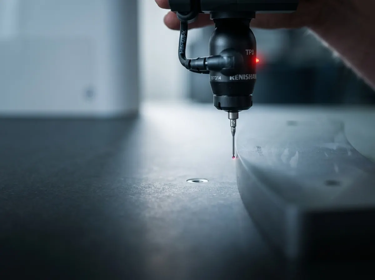
CMM dimensional inspection
FTL's Coordinate Measuring Machine capability supports dimensional verification of friction and associated components against the agreed drawing or component definition. The scope can identify critical dimensions, geometric features, component revision, applicable tolerances, inspection frequency, required records and acceptance responsibility.
Shear testing of bonded components
Where a friction material is bonded to a backing plate or associated component, shear testing can form part of development evidence, prototype evaluation, process validation and production-quality control. The test must define component configuration, friction and backing materials, surface preparation, bonding route, sample quantity, method, units and acceptance criterion.
In-process quality checks
Checks can be defined at relevant stages such as material manufacture, machining, surface preparation, bonding, finishing and assembly.
Visual and final assembly inspection
Final checks can review visible component condition, component configuration, bonded assembly, applicable finish, assembly, customer-specific identification and packaging or protection requirements.
Batch, lot and production traceability
The agreed manufacturing route can maintain traceability across material reference and revision, production batch or lot, component revision, machining, bonding, finishing, testing, inspection, storage and dispatch.
What to bring to the first testing or inspection discussion
Begin with the decision the evidence must support. FTL can then confirm which test, inspection or further application information is required.
The engineering question
Explain what the project needs to decide, such as:
- Whether a material variant should progress
- Whether a replacement material is a credible route
- Whether a prototype matches the agreed geometry
- Whether a bonded configuration meets an agreed criterion
- Whether variation exists between components or batches
- Whether a production route is ready for repeat manufacture
The application
Share:
- What equipment or system the component belongs to
- What function the material or component performs
- Whether it brakes, holds, locks, damps or controls motion
- Whether the application is new, existing or obsolete
- What has prompted the test or inspection requirement
The sample or component
Identify:
- Material reference and revision
- Component revision
- Sample form and dimensions
- Backing or associated component
- Bonded construction and mating surface
- Current condition and sample quantity
The relevant conditions
Where known, provide:
- Load or pressure
- Speed
- Temperature
- Contamination
- Operating sequence
- Test duration and number of cycles
- Required braking or holding behaviour
Available baseline evidence
This can include:
- Technical data sheet
- Drawing or specification
- Existing test result
- Previous inspection report
- Current component
- Customer acceptance criteria
- Production or batch record
- Known service history
The required output
Confirm whether the customer needs:
- A material comparison
- Test result
- Inspection record
- Dimensional report
- Shear-test result
- Production evidence
- Traceability record
- Information to support a customer approval process
Responsibility and validation context
The project should state:
- What FTL will test or inspect
- What the customer will evaluate
- Which party defines acceptance
- Which party holds design authority
- Whether further system-level or regulatory work is required
A complete test specification is helpful but is not mandatory for the first conversation.
Define the question, conditions and decision before testing begins
Testing should produce evidence that can be interpreted against an agreed requirement.
| Test-plan field | What the project should define |
|---|---|
| 01Engineering question | What decision must the evidence support? |
| 02Sample | Which material, component, revision and quantity will be assessed? |
| 03Mating component | Which surface or associated component forms part of the test? |
| 04Conditions | What load, pressure, speed, temperature, contamination or sequence applies? |
| 05Measurement | What property or dimension will be recorded? |
| 06Units | How will the result be expressed? |
| 07Baseline | Is the result compared with an existing material, component or requirement? |
| 08Acceptance criterion | What result allows the project to progress? |
| 09Responsibility | Who defines, witnesses, reviews and approves the result? |
| 10Next decision | Will the result trigger progression, refinement, retesting or rejection? |
| 11Record | What report or production evidence must be retained? |
A test programme should not begin with an unqualified request to "prove performance". The project must identify which performance characteristic, under which conditions, for which component configuration and against which acceptance criterion.
A controlled path from engineering question to production evidence
The sequence varies by project, but every stage should produce enough information to support the next decision.
Establish technical fit
- Application
- Material or component
- Current stage
- Available evidence
- Required decision
Define the evidence level
- Material level
- Component level
- Production level
- Customer or system level
Define the engineering question
- Compare material routes
- Assess coefficient stability
- Review wear behaviour
- Verify dimensions
- Assess a bonded sample
- Confirm production conformity
Confirm the sample and configuration
- Material reference and revision
- Component revision
- Sample geometry, mating surface
- Backing component, bonding route
- Finish, quantity, condition
Agree conditions and measurement method
- Load or pressure
- Speed, temperature
- Test sequence
- Duration or cycles
- Measured output, units
- Required inspection points
Agree acceptance criteria and responsibilities
- Acceptance range or limit
- Comparison baseline
- Who reviews and approves
- Further validation needed
- Required document output
Prepare or manufacture the samples
- Material samples
- Machined friction components
- Associated metallic components
- Bonded components
- Prototype or production samples
Complete baseline inspection
- Visual inspection
- Dimensional inspection
- Material or component identification
- Sample-condition record
- Confirm component revision
Complete the agreed test or inspection
- Material testing
- Dynamic testing
- CMM inspection
- Shear testing
- In-process inspection
- Final inspection
Review the results against the criteria
- Result and conditions
- Sample configuration
- Baseline
- Acceptance criterion
- Test limitations, evidence gaps
Refine and repeat where necessary
- Formulation
- Component geometry
- Bonding route
- Manufacturing process
- Test conditions
- Inspection requirements
Support customer or system validation
- FTL supplies evidence within its agreed scope
- Customer or appointed authority completes equipment, platform, operational or regulatory evaluation
Establish production inspection and traceability
- Production and inspection frequency
- Test frequency
- Material and component revision
- Batch or lot traceability
- Change-control responsibilities
Assess friction behaviour within defined test conditions
Friction behaviour can change with the material, mating surface, load, speed, temperature, component construction and test sequence. The project should therefore define the conditions and decision criteria before interpreting a coefficient or wear result.
Coefficient-stability evidence
01The test scope should identify:
- Whether the relevant behaviour is dynamic, static or both
- Load or pressure, speed, temperature
- Mating surface, test duration, conditioning
- Measured range and acceptance criterion
Wear evidence
02Wear assessment should define:
- Starting sample dimensions or mass
- Test conditions and contact configuration
- Measurement method and units
- Test duration or cycles
- Comparison basis and acceptance criterion
Thermal-performance evidence
03The project should identify:
- Temperature range
- Heating rate or sequence
- Cooling or recovery sequence
- Continuous or intermittent context
- Friction or wear property being assessed
- Acceptance criterion
Comparative material testing
04Where agreed, testing can compare:
- Current and proposed material
- Established and optimised formulation
- Multiple development variants
- New and legacy material routes
Test limitations
The result should state the sample tested, configuration, test conditions, equipment or method, measurement uncertainty where required, deviations, applicable limitations and whether further customer or system validation is required.
CMM dimensional inspection for prototype and production components
FTL uses Coordinate Measuring Machine inspection to verify relevant component geometry against the agreed drawing or component definition. CMM inspection supports dimensional evidence. It does not manufacture the component and should not be described as "CMM machining".
Prototype inspection
CMM can support review of new prototype geometry, redeveloped legacy components, comparative component variants, features affecting fit or assembly, and components proceeding to testing.
Production inspection
The agreed production route can define characteristics to inspect, inspection stage, sample quantity or frequency, drawing or component revision, applicable tolerance, required record and acceptance responsibility.
Critical dimensions and interfaces
Depending on the project, inspection may focus on mounting features, locating features, component profile, bonded or assembled interfaces, mating surfaces, thickness or geometry relevant to the application, and customer-defined characteristics.
Drawing and design comparison
Before inspection, confirm the controlled drawing or model, revision, design authority, applicable tolerances, inspection datum or reference approach, and customer acceptance process.
Inspection output
The agreed deliverable may include recorded measured characteristics, comparison with specified values, inspection date, component or sample identification, drawing revision, batch or lot reference, and acceptance status within the agreed scope.
CMM inspection does not by default include
- laser scanning
- non-contact scanning
- automatic reverse engineering
- First Article Inspection Reports
- PPAP
- ISO 17025-accredited measurements
- a universal measurement uncertainty
- or a specific tolerance capability
Each of these must be confirmed separately for the project.
Assess a defined bonded component against an agreed shear criterion
Shear testing can form part of the evidence route where a friction material is bonded to a backing plate or associated component. The result applies to the tested material, substrate, surface preparation, bonding route, sample geometry and test conditions.
Development testing
Shear testing may support comparison or assessment of:
- Prototype bonded components
- A proposed material and backing-component combination
- Surface-preparation routes
- Bonding-process development
- A redeveloped legacy component
Production-quality testing
Where agreed, shear testing can form part of the production-control route for a defined bonded configuration. The project should establish:
- Test frequency and sample source
- Component revision
- Bonding-process revision
- Acceptance criterion
- Record and traceability requirements
Required inputs
Define friction material, backing-component material, component geometry, surface preparation, bonding system, cure route, sample dimensions, sample quantity, test method, units and acceptance criterion.
Interpretation boundary
A shear result does not automatically establish:
- Complete brake performance
- Service life
- Thermal behaviour
- Environmental durability
- Every bonded geometry
- System or regulatory approval
Carry approved requirements into repeat manufacture
Development evidence must be translated into production controls if the approved material and component route is to be repeated consistently.
Incoming or pre-process identification
Where included in the control route, confirm material reference and revision, associated-component reference, component revision, batch or lot identity, and required documentation.
In-process checks
Checks can be positioned at relevant stages such as material production, machining, surface preparation, bonding, curing, finishing and assembly. The project should define the characteristic, method, frequency and acceptance criterion.
Final component inspection
Final inspection can review component configuration, relevant dimensions, visible condition, bonded assembly, finish, assembly, identification, and packaging or protection requirements.
Production documentation
Depending on scope, records can identify material reference and revision, component revision, production batch, applicable process stages, test or inspection results, final inspection status, and storage and dispatch reference.
Batch and lot traceability
Traceability can connect the finished component with the relevant material, production batch, machining, bonding, finishing, testing, inspection, storage and dispatch.
Change control
The approved production route should identify how changes to the material formulation or revision, component geometry, backing component, bonding or finishing route, test or inspection requirement, supplier or process input, and customer-approved configuration are reviewed.
What a testing and inspection engagement can deliver
Deliverables must be agreed before work begins. Not every project includes every item below.
Test or inspection scope
Can define the engineering question, sample or component configuration, test or inspection conditions, measured characteristics, acceptance criteria, customer and FTL responsibilities, and required records.
Material-test evidence
Depending on scope, outputs may relate to coefficient stability, wear rate, thermal performance, comparison between material variants, and a recommendation for the next development stage.
Dynamic-test record
Can identify sample, test configuration, conditions, measured result, units, acceptance criterion, limitations and review outcome.
CMM inspection evidence
Can include agreed dimensional measurements linked to component identification, drawing or model revision, specified dimensions, applicable tolerances, inspection date, and batch or lot reference.
Shear-test evidence
Can identify bonded configuration, material and associated component, surface preparation, bonding-process reference, test method, result, units and acceptance criterion.
Production inspection records
Depending on scope, records can cover in-process checks, final visual inspection, final assembly inspection, component identification, production status, and batch or lot traceability.
Engineering-review outcome
The review can recommend progression to the next project stage, further development, repeat testing, a different material or component route, additional customer or system-level validation, or transfer into controlled production.
Keep testing and inspection connected to the manufactured component
Testing can become disconnected from production when the material developer, component manufacturer, bonder, test provider and inspector operate separately. FTL connects the agreed evidence route with the material, component and production processes it is intended to control.
Actual lead-time, administrative or cost benefits depend on your current supplier arrangement and the agreed FTL scope.
Testing and inspection within three engineering project routes
New Programme Support
Testing and inspection can support development, prototype and validation decisions across a new material or component programme.
Legacy & Obsolete Component Reverse Engineering
Testing and inspection can support dimensional review, replacement-material assessment, revalidation and controlled repeat supply.
Friction System Performance Optimisation
Testing and inspection can help investigate inconsistent braking, wear, thermal performance and component variation.
Testing and inspection for regulated and demanding applications
The required evidence differs by application, programme and approval route.

Aerospace
Material, dimensional, bonded-component and production evidence for braking, locking, actuation and motion-control applications where traceability and approval responsibilities must be explicit.
Aerospace Friction Materials & Components →
Defence
Testing and inspection support for programmes where supplier assurance, controlled information, documentation, traceability and continuity matter.
Defence Friction Materials & Components →
Wind Energy
Material, component and production evidence for yaw-brake development, performance review and obsolete-component replacement.
Wind Turbine Friction Materials & Components →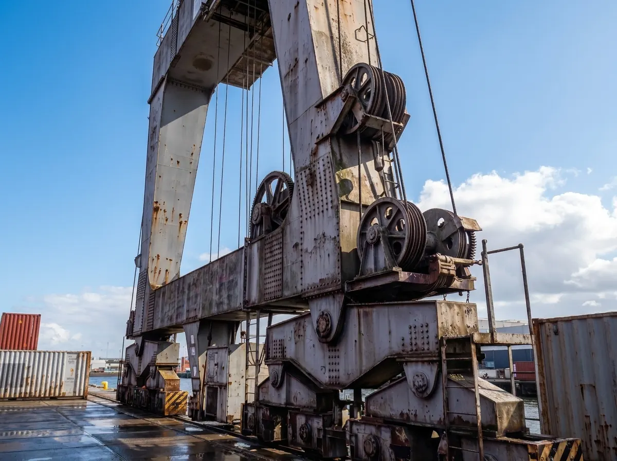
Industrial Equipment
Testing and inspection for industrial braking, crane, motor, safety-equipment and general motion-control applications.
Industrial Friction Materials & Components →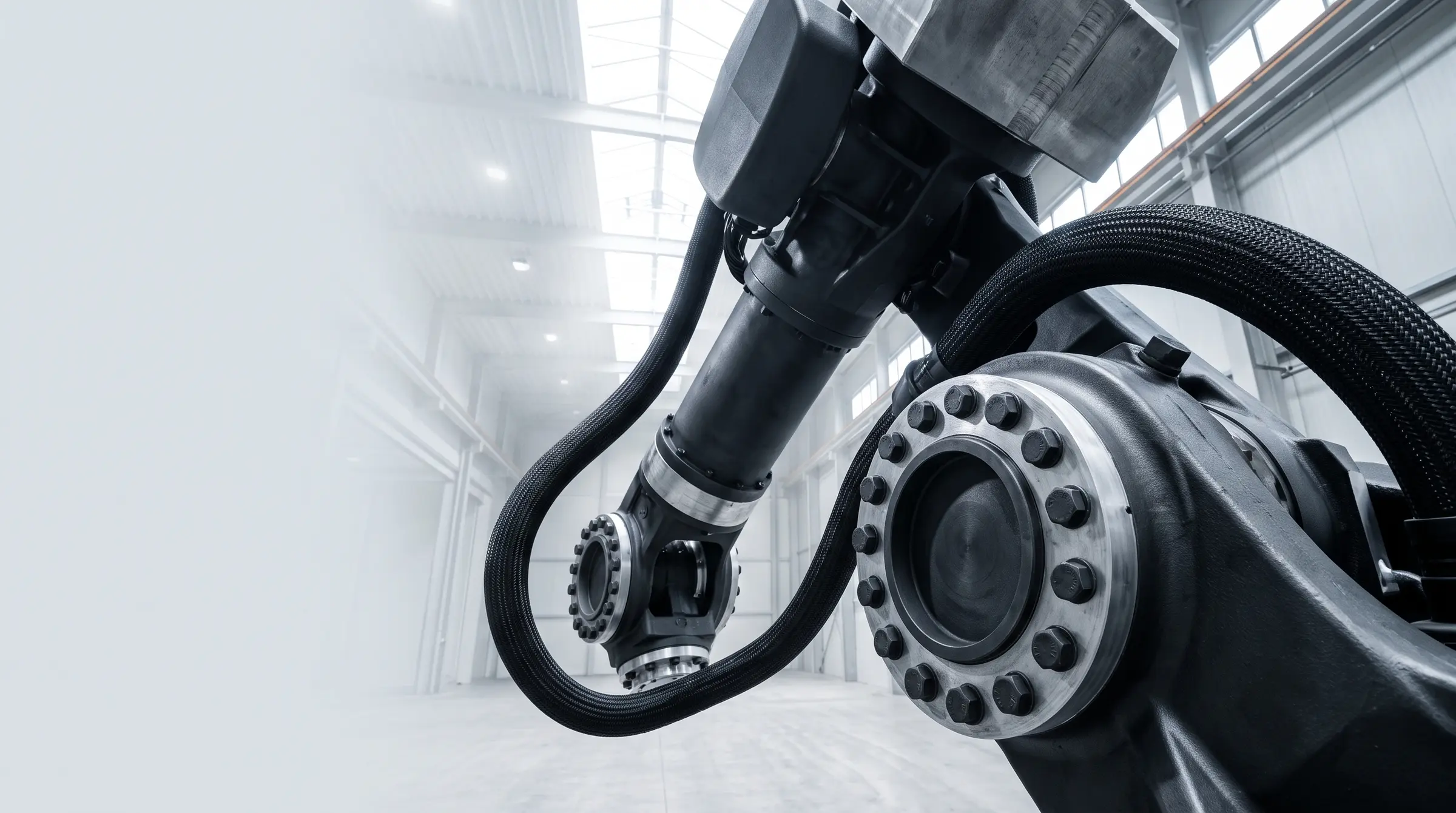
Robotics
Material, dimensional and production evidence for holding and braking components used in robotic joints and robotic arms.
Robotics Friction Materials & Components →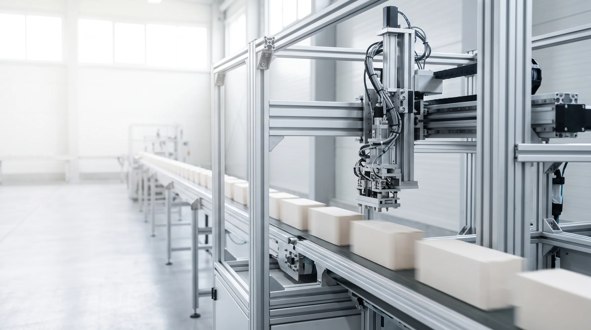
Industrial Automation
Testing and inspection for servo motor brakes, electromagnetic brakes and high-cycle clutches, including cycle-life assessment.
Automation Friction Materials & Components →The evidence buyers need before approving a material or component route
Can FTL match or improve the required performance?
FTL can review the existing material or component, operating conditions, required behaviour, available test evidence, proposed route and acceptance criteria. Whether current performance can be matched or improved depends on the agreed development, testing and validation route. No result should be guaranteed before that evidence is produced.
Is the proposed solution already proven in service?
Where relevant approved application history exists, FTL can identify it during the technical discussion. A new, changed or redeveloped application may still require material testing, component inspection, customer evaluation, system-level testing or programme-specific approval. Laboratory or component evidence is not in-service proof.
How does FTL support quality and repeatability?
The agreed route can connect a controlled material reference, component revision, manufacturing processes, in-process checks, material or component tests, final inspection, production records, and batch and lot traceability. The exact controls and acceptance criteria must be agreed for the project.
Does FTL have the engineering capability to interpret the results?
FTL's testing and inspection activities are connected with material formulation, engineering and design, CNC machining, bonding and finishing, prototype manufacture and repeat production. The evidence can therefore support a defined engineering or production decision rather than exist as an isolated measurement.
SDTS approached FTL after an original aircraft brake pad became unavailable. FTL redesigned and manufactured a replacement component using a material aligned with the stated aeronautical technical requirements, supporting SDTS's route to a certifiable aircraft modification.
“The quality of the manufactured product is remarkable.”
Olivier Moulin 





What organisational proof exists?
Company standards and registrations
The SDTS case demonstrates component engineering and manufacture rather than any specific FTL test, inspection method or test machine.
Is FTL the right testing and inspection route?
FTL is a strong fit when:
- The requirement is connected to a friction material or complete component
- Testing must support a new programme, redevelopment or performance review
- The samples can be linked to a controlled material or component revision
- The engineering question and acceptance requirement can be defined
- Prototype manufacture may also be needed
- CMM, shear, material or dynamic evidence forms part of the route
- Production checks and traceability matter
- The approved solution may progress into repeat manufacture
- You want testing, inspection and manufacturing connected through one supplier
FTL must confirm fit when:
- A particular test standard is mandatory
- A specific machine or sensor is required
- The required load, speed or temperature range is not yet confirmed
- Environmental or contamination simulation is required
- Customer witnessing is required
- Independent or accredited laboratory status is required
- A specific CMM accuracy, envelope or report format is mandatory
- The test uses a customer-supplied sample or mating component
A different route may be required when:
- An independent ISO/IEC 17025-accredited laboratory is mandatory
- Complete vehicle, turbine, aircraft or equipment testing is required
- Regulatory certification testing is required
- Full brake-system dynamometer testing is required
- Field testing is required
- The requirement is unrelated to an FTL material or component route
- The customer wants a measurement without sufficient sample, drawing or acceptance information
Frequently asked questions about friction-material testing and inspection
What friction-material testing can FTL support?
What is dynamic friction testing?
Can FTL measure coefficient of friction?
Why can friction coefficient change between tests?
Can FTL test wear rate?
Can FTL test thermal performance?
Does FTL provide brake dynamometer testing?
Does FTL test noise, vibration or harshness?
Can FTL simulate complete real-world operating conditions?
Can FTL accelerate long-term wear testing?
What is CMM inspection?
Is CMM inspection the same as CMM machining?
Can FTL use CMM inspection for reverse engineering?
What CMM reports can FTL provide?
Is FTL's CMM inspection ISO/IEC 17025 accredited?
What is shear testing used for?
Does a shear test guarantee bond performance in service?
Can FTL test customer-supplied samples?
Can FTL compare two friction materials?
Can FTL inspect prototype components?
Can FTL support production-batch testing?
Does FTL provide full traceability?
Does an FTL test result provide final system approval?
How long does testing or inspection take?
When are price and sample quantity discussed?
Can FTL support customers outside the UK?
Ask an FTL engineer about testing and inspection
A part number, a machine, or the problem in your own words.
Start with the engineering question the evidence must answer
Tell FTL what the material or component must demonstrate, what samples or drawings are available and what decision the results need to support. A short initial brief is enough.
The relevant technical and engineering team members can then review the sample, conditions, inspection requirements, acceptance criteria and most appropriate next step.
Optional drawing, specification or existing test-information upload available.